
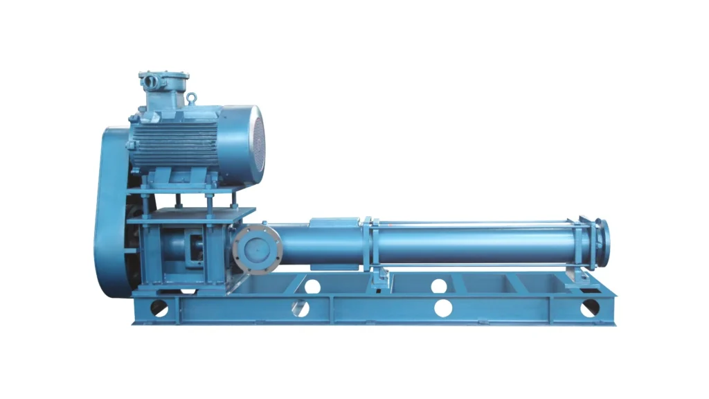
Short answer: progressive cavity pump selection starts with the fluid, not the model number. Define viscosity at pumping temperature, solids, abrasiveness and chemistry first. Those set the pump size and number of stages, the running speed, the stator elastomer and the inlet arrangement. Then protect the pump against dry running and overpressure, because a progressive cavity pump must never run dry.
This guide walks through each decision, shows how CTP’s eccentric helical rotor series map to typical duties, and lists the data to send with a request for quotation.
What is a progressive cavity pump?
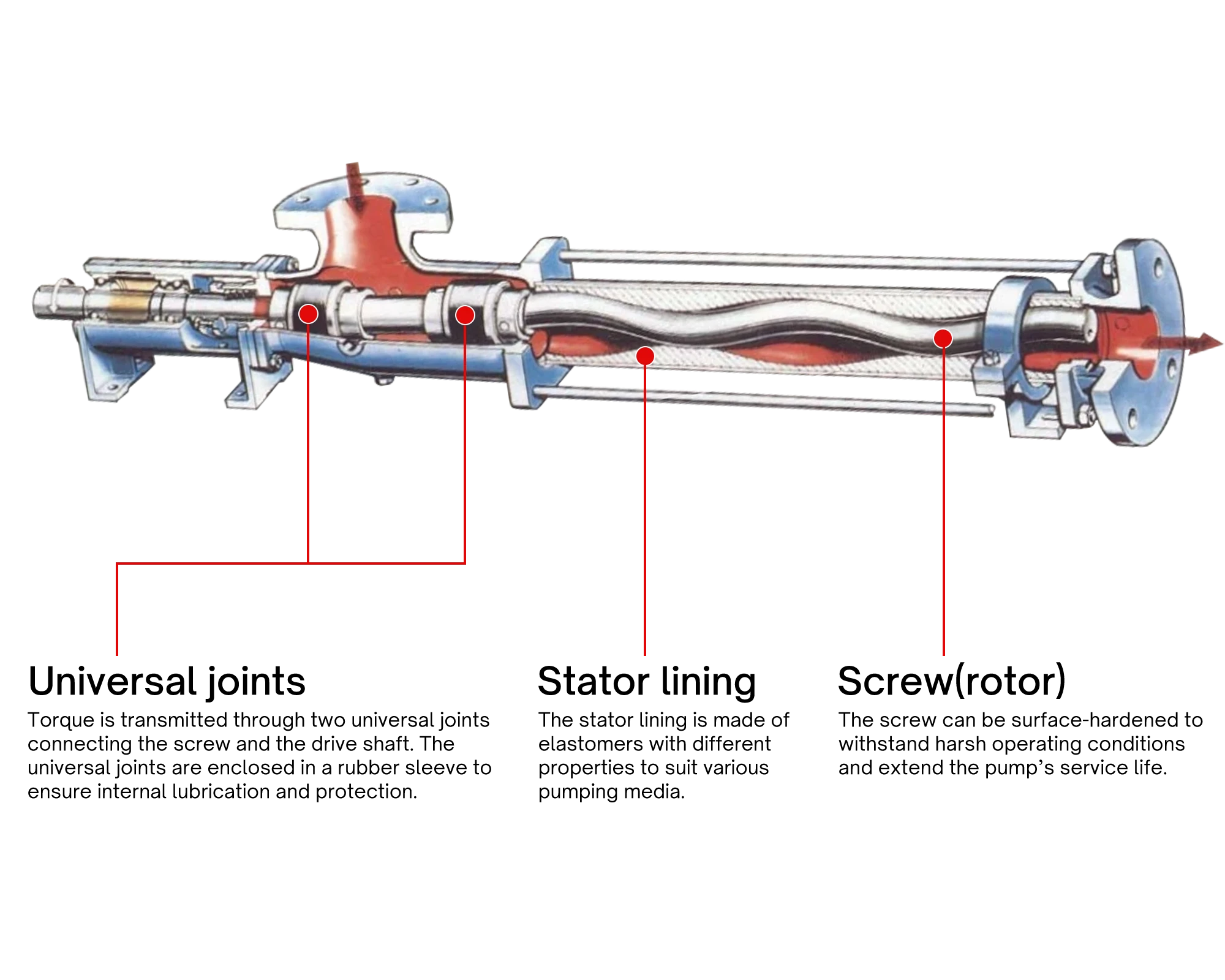
A progressive cavity pump is a rotary positive-displacement pump. A single-start helical rotor turns inside a double-start helical stator made of elastomer. As the rotor turns with an eccentric motion, it forms sealed cavities with the stator that travel steadily from suction to discharge. The same design is called an eccentric screw pump, a helical rotor pump or a single screw pump. CTP calls its range eccentric helical rotor pumps.
Because the rotor moves eccentrically, the drive passes through a connecting shaft. In CTP pumps this shaft has two universal joints protected by rubber jackets. Flow is roughly proportional to speed. Actual delivery also depends on differential pressure, viscosity, slip and inlet filling.
CTP’s single screw family is self-priming and simple in construction. It can handle neutral or corrosive, clean or abrasive, fibre-laden and high-solids liquids, gas-containing liquids and pastes that do not flow on their own. Published family limits are up to 400 m³/h, 2.4 MPa (EP series up to 8.0 MPa), 150 °C and viscosities up to 2.7×10⁵ cSt. Those limits describe the range, not one pump.
When to choose a progressive cavity pump, and when not to
Consider a single screw pump when one or more of these apply:
- The liquid is very viscous or does not flow readily into a suction port.
- It carries suspended solids, abrasive particles or short fibres.
- It is shear-sensitive and should be moved with little agitation.
- The process needs steady, low-pulsation flow that can be adjusted by speed.
- Gas or air enters the liquid intermittently.
For clean, lubricating oils at higher pressure, a three screw pump is usually the better fit. For large-flow cargo or crude oil transfer, twin screw pumps take over. Our screw pump selection guide for oil and gas compares single, twin and three screw pumps by duty. Gear pumps need a lubricating liquid without solids; see screw pump vs gear pump. On ships, single screw pumps are used where bilge water carries sludge; see our marine bilge pump page.
Step 1: define the fluid precisely
Give the fluid name, composition and a current safety data sheet. Add density and viscosity at the minimum, normal and maximum pumping temperature, not only at room temperature. If viscosity changes with shear rate, send a viscosity curve.
For solids, report concentration, maximum particle size, particle shape and hardness. For fibres, give type and length. If gas can enter, state the expected volume fraction and whether it is continuous or intermittent. Soft suspended material, hard grit and long fibres create different risks, so concentration alone is not enough. The general data every pump supplier needs is covered in what engineers need before choosing a pump.
Step 2: flow, pressure and number of stages
State normal, minimum and maximum flow and the operating hours. Then calculate the real differential pressure: discharge pressure, static elevation and line losses, minus suction pressure.
In a progressive cavity pump, pressure capability comes from the number of stages, meaning the length of the rotor and stator. More stages spread the pressure across more sealing lines, which reduces slip and wear at each stage. CTP’s EH family shows the pattern:
| Series | Maximum pressure | Maximum flow |
|---|---|---|
| EH | 0.6 MPa | 300 m³/h |
| E2H | 1.2 MPa | 140 m³/h |
| E3H | 1.8 MPa | 71 m³/h |
| E4H | 2.4 MPa | 30 m³/h |
If the duty sits near the top of a stage’s pressure rating with an abrasive fluid, selecting the next stage up usually gives longer stator life. For high pressure at small flow, the EP series reaches 8.0 MPa.
Step 3: running speed and abrasive media
Speed is the main lever on wear. The rotor slides against the stator on every turn, so wear from abrasive particles rises quickly with speed. For abrasive duties, a larger pump running slower normally outlasts a smaller pump running fast at the same flow.
Viscosity pushes in the same direction. Very thick liquids need time to fill each cavity, so speed has to come down as viscosity rises. CTP’s ER hopper-inlet pumps for non-flowing media are rated at up to 500 rpm.
For abrasive service the rotor can be supplied hardened. Combine that with a conservative speed and, where pressure is high, an extra stage. If you plan to control flow with a variable-speed drive, check the whole speed range against suction conditions and wear, not only the top speed.
Step 4: stator elastomer selection
The stator is the part most affected by the fluid. CTP selects the stator elastomer for each liquid. The table below is general engineering guidance on common elastomer families. Final compatibility is confirmed against your safety data sheet and temperature.
| Elastomer family | Commonly considered for | Watch out for |
|---|---|---|
| Nitrile (NBR) | Mineral oils, fuels, oily sludge, many water-based media | Strong oxidisers, ketones and aromatic solvents |
| EPDM | Hot water, many dilute acids and alkalis | Mineral oils and fuels, which cause swelling |
| Fluoroelastomer (FKM) | Hydrocarbons, many solvents and chemicals, higher temperatures | Lower abrasion resistance and higher cost |
| Natural rubber | Abrasive water-based slurries at moderate temperature | Oils, fuels and higher temperatures |
Two points are often missed. First, elastomers swell with temperature and some chemicals, which tightens the rotor-to-stator fit and raises starting torque. The fit is chosen for the actual operating temperature, so give the full range. Second, the shaft seal and universal-joint jackets also touch the liquid, so check them too.
Step 5: choose the arrangement — CTP series overview
With the fluid, pressure, speed and elastomer defined, the physical arrangement can be shortlisted. Series names indicate a starting point; the duty review decides.
| Series | Arrangement | Published limits | Typical fit |
|---|---|---|---|
| G | General-purpose | Up to 130 m³/h, 1.2 MPa | General process transfer, sludge and wastewater |
| EH / E2H / E3H / E4H | Standard to multi-stage | 300 / 140 / 71 / 30 m³/h at 0.6 / 1.2 / 1.8 / 2.4 MPa | Sludge and process duties, rising pressure |
| EL / E2L | Compact | Confirmed per duty | Limited axial space; viscous or fibrous transfer |
| ER / E2R / E4R | Hopper (funnel) inlet | Up to 500 rpm | Thick, non-flowing sludge and pastes |
| ES / E2S | Easy-clean | Confirmed per duty | Processes that need frequent cleaning and disassembly |
| EU / E2U | Vertical submersible | Confirmed per duty | Tanks, pits and sumps |
| EP | High pressure, small flow | Up to 8.0 MPa | High-pressure, low-flow viscous process duties |
| MEH | Large capacity | Up to 400 m³/h | High-flow sludge and process liquid transfer |
| GS | Small easy-clean pump | Confirmed per duty | Small easy-clean duties; not a sludge pump |
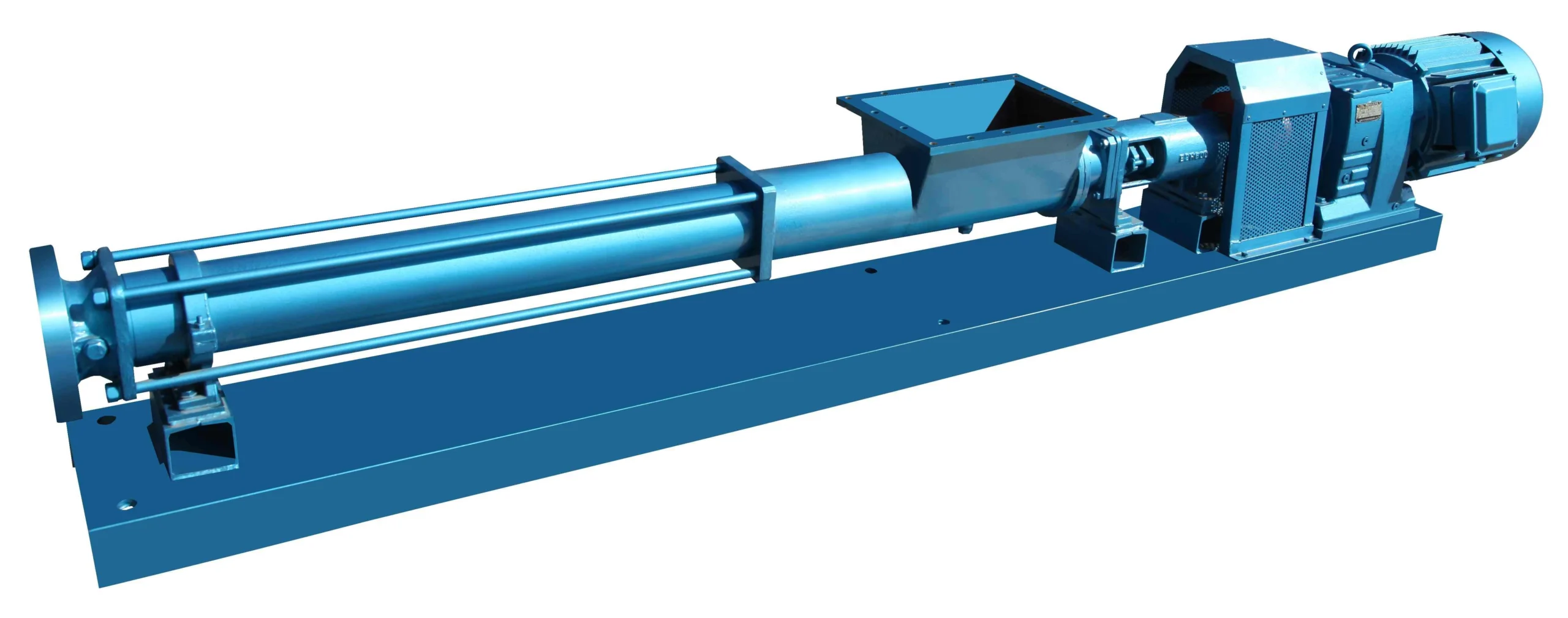
For sludge, wastewater and oily residues, the core choices are G, the EH family, the ER family for non-flowing material and the EU family for tanks and pits. EL, EP and MEH cover compact, high-pressure and high-flow cases. Full product details are on the eccentric helical rotor pump page.
Dry running and overpressure: protect the pump
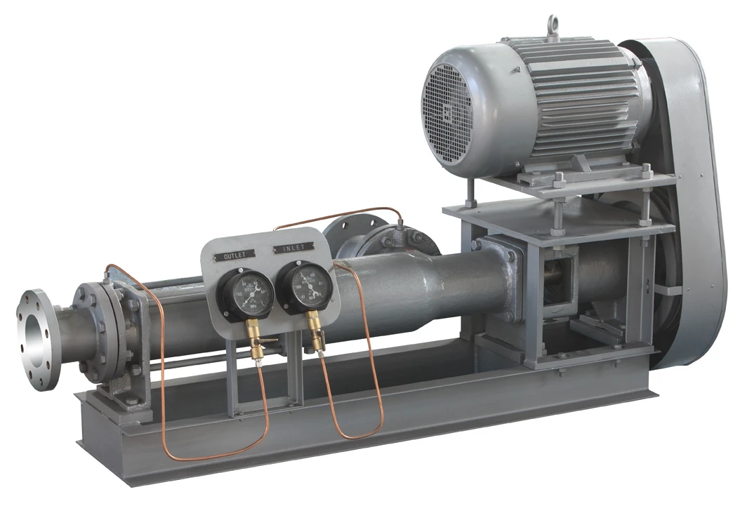
A progressive cavity pump must not run dry. The pumped liquid lubricates and cools the rotor-to-stator contact. Without it, friction heats the elastomer within a short time and can burn or tear the stator. Self-priming does not change this: the pump can draw liquid up a suction line, but the stator must already be wetted.
Common protection measures in general practice:
- Fill the pump with liquid before the first start and after maintenance.
- Fit a dry-run sensor, such as a stator temperature sensor or a flow switch, or a low-level cut-out on the supply tank.
- Keep the suction line short, correctly sized and free of air leaks.
Overpressure is the second risk. A positive-displacement pump keeps pushing against a closed or blocked discharge until something fails. Provide a pressure relief valve or pressure switch on the discharge. Never start against a closed discharge valve. Check rotation direction before operation, as specified for the series.
Common selection mistakes
- Using room-temperature viscosity. Start-up, winter or process conditions may be far thicker. Give the worst case.
- Ignoring how the fluid reaches the rotor. A pump cannot deliver what does not fill its cavities. Non-flowing media may need a hopper inlet or feeding aid.
- Running too fast on abrasives. A small, fast pump is cheaper to buy and costlier to keep running.
- Choosing the elastomer from the fluid name alone. Composition, concentration and temperature decide.
- Selecting from maximum catalogue data. Published limits describe the range, not a guaranteed operating point for every fluid and material combination.
Progressive cavity pump RFQ checklist
- Fluid name, composition and safety data sheet
- Viscosity and density at minimum, normal and maximum temperature
- Solids concentration, maximum size, hardness and fibre details; gas content
- Minimum, normal and maximum flow, and operating hours
- Suction and discharge pressure, elevation and piping details
- Flow-control method (fixed or variable speed) and power supply
- Installation arrangement, available space and cleaning method
- Seal requirements, hazardous-area needs and documentation or inspection scope
FAQ
Is a progressive cavity pump the same as an eccentric screw pump?
Yes. Progressive cavity pump, eccentric screw pump, helical rotor pump and single screw pump all describe the same rotor-and-stator positive-displacement design. CTP uses the name eccentric helical rotor pump.
Can a progressive cavity pump handle high-viscosity fluids?
Yes. CTP’s single screw family is published up to 2.7×10⁵ cSt, and hopper-inlet ER pumps handle media that do not flow on their own. Suitability depends on inlet filling, speed, pressure and drive power at the actual temperature.
How do I reduce stator wear with abrasive media?
Run the pump slower, which usually means a larger size for the same flow. Add a stage if pressure is high, use a hardened rotor and choose an elastomer suited to the fluid and temperature.
Can a progressive cavity pump run dry?
No. Dry running quickly overheats and damages the stator. Fill the pump before starting and fit dry-run protection such as a stator temperature sensor, flow switch or tank low-level cut-out.
Which CTP series should I use for sludge?
The G series, EH family, ER family (non-flowing sludge) and EU family (tanks and pits) are the core choices, with EL, EP and MEH for compact, high-pressure or high-flow cases. GS is a small easy-clean pump and is not intended for sludge.
Request a series-specific selection
CTP has built eccentric helical rotor pumps on technology licensed from Bornemann (Germany) since 1993. Send your fluid data, flow, pressure and installation details through pump selection assistance, and our engineers will recommend the series, number of stages, speed and stator elastomer. For other questions, contact CTP Pumps.
Published by CTP Pumps · Sources: CTP product brochure (single screw pump data); general progressive cavity pump engineering practice; Wikipedia, “Progressive cavity pump” · Last reviewed: October 12, 2026